




How to match lightweight wall panel machine capacity to project demand
A lightweight wall panel line should be sized from the project’s required installed panel output, not from the machine’s highest published hourly capacity. The practical starting point is to convert the construction schedule into panels per shift, then test whether that rate still holds after allowing for changeovers, curing time, material preparation, rejects, and planned maintenance. A line that appears adequate on a nameplate can become the project bottleneck once multiple panel lengths, openings, or density grades are introduced.
This issue usually becomes visible when the site programme calls for rapid wall installation but the factory plan is based only on total square metres. Panels may be delayed because molds are occupied, the curing area is full, slurry supply cannot keep up, or finished panels need extra handling before dispatch. Matching a lightweight wall panel machine to demand therefore requires a capacity model for the entire production flow rather than a comparison of one machine specification against one project quantity.
Start with the demand that must leave the factory
Technical evaluation should begin with the delivery requirement: how many acceptable panels of each type must be available for shipment in each period? “Acceptable” matters. Gross molding output is not the same as the number of panels that can pass inspection, be stored safely, and arrive at the installation area on time.
Build the demand calculation from the project’s wall schedule and separate it by panel family. A solid lightweight partition panel, a hollow-core panel, and a panel with embedded service provisions may use similar materials but can have different cycle times and handling requirements. Do not combine them into one average panel unless their dimensions, mold occupancy, curing route, and finishing work are genuinely similar.
A useful planning sequence is:
- Determine the required wall area by panel type and installation phase.
- Convert wall area into panel quantities using actual panel widths and lengths.
- Allow for cutting losses, site damage, inspection rejects, and contingency stock where applicable.
- Divide the required quantity by available production days, then by planned shifts.
- Compare that net shift requirement with sustainable output, not theoretical maximum output.
For example, a schedule can look manageable when expressed as monthly square metres, yet become demanding when delivery is concentrated into short installation windows. Capacity should be checked against the peak demand period. A line selected around the monthly average may leave little recovery room after a material interruption or an unplanned stoppage.
Define capacity in panels, area, and cycle time
Machine suppliers may state capacity in square metres per day, panels per mold cycle, or output per year. Each format can be useful, but none is sufficient without the assumptions behind it. Evaluators should ask what panel size, thickness, density, shift arrangement, mold configuration, and operating time were used to derive the stated number.
The basic relationship is straightforward:
Net daily output = panels released per cycle × usable cycles per day × panel area × yield
The difficulty lies in defining “usable cycles.” A theoretical calculation may use every hour in a shift. A workable calculation allows time for cleaning, mold preparation, reinforcing or inserting components where required, casting, vibration or compaction, demolding, transfer, inspection, and interruptions. If a line has several stations, the slowest station establishes the effective rhythm.
For capacity matching, record at least the following variables:
Find the real constraint before choosing a larger line
It is easy to focus on the panel-forming machine because it is the most visible item in the line. In practice, the limiting point may sit upstream or downstream. Increasing molding speed does not solve a curing bottleneck. Adding molds does not help if the overhead lifting system cannot clear finished panels at the necessary frequency. Raising slurry output can create waste if the casting station is not ready to receive it.
Map the route from raw material arrival to loaded finished panels. At each step, identify throughput, buffer capacity, and the consequence of a delay. The key question is not “Which machine is slowest?” but “Which operation prevents the next panel from being released?”
Material preparation can cap panel output
Lightweight panel recipes often depend on controlled proportions of cementitious material, aggregates or fillers, water, fibers, foaming components, and other additives. The mixing system must provide consistent batches at the rate demanded by casting. A mixer with inadequate working volume may force pauses between mold fills. A system that is oversized but poorly matched to batch size can also create control problems, especially where small recipe changes are needed.
Assess the material side by batch volume, actual mixing time, discharge time, cleaning time, and the number of batches required per mold cycle. Include the travel path from mixer to mold. Pumping distance, elevation changes, transfer hoppers, and waiting time can affect the actual delivery rate. The slurry must remain workable throughout the casting window; capacity that relies on holding mixed material too long is not dependable capacity.
Curing is often a hidden scheduling problem
Panel lines are sometimes assessed around mold output alone, while curing positions are treated as a secondary detail. Yet each mold or panel occupies space for a defined period before it can move forward. If curing time exceeds the assumed production cycle, molds may not return to casting when needed. The line then loses output even though every individual station is functioning normally.
Check whether curing capacity is expressed as a number of positions, total panel area, or a planned release sequence. The evaluation should include the longest expected curing route, not only the most favorable recipe. Temperature control, humidity, seasonal conditions, and the timing of demolding all influence how quickly molds can re-enter service. Where panel strength at handling is critical, do not assume an earlier release merely to satisfy a nominal output target.
Handling equipment must match panel geometry
Lightweight panels are easier to transport than conventional masonry units, but large-format panels still require controlled lifting and support. The handling system must accommodate panel length, width, thickness, center of gravity, and the required orientation during demolding, stacking, storage, and loading.
A mismatch here can reduce line capacity in less obvious ways. Operators may need to wait for lifting equipment, use slower movements to avoid edge damage, or limit stacking height because of panel strength and storage conditions. Confirm the working envelope of cranes, clamps, vacuum lifters, transfer carts, or other lifting devices against the largest panel in the specification—not only the most common panel.
Use sustainable utilization, not nameplate utilization
A line selected at almost full rated output gives little flexibility for ordinary factory realities. Tool cleaning, planned inspections, recipe adjustments, mold maintenance, material delivery variation, and product changeovers are part of normal operation. They should not be treated as exceptional events.
Instead of assuming that every shift runs at its highest possible rate, establish a utilization factor based on the planned operating regime. The exact allowance depends on line design and product range, but the purpose is consistent: capacity must include recoverable time. A production plan with no margin can meet its target only when every process remains ideal, which is rarely an acceptable basis for a project-dependent supply commitment.
Capacity margin does not necessarily mean buying the largest available equipment. It can come from extra molds, a staged curing area, a buffer for prepared material, a second shift during peak demand, or a layout that permits a later expansion. The appropriate choice depends on where the constraint appears and whether future demand will be steady, seasonal, or project-based.
Choose automation according to variation, not just labor reduction
Automation is often evaluated as a direct substitution for manual work. That view is incomplete. Its main value in panel production may be repeatability: more stable dosing, controlled mold movement, consistent timing, traceable operating parameters, and less variation between shifts. Those benefits can protect usable output when the project has tight dimensional or surface-quality expectations.
However, higher automation can be less suitable when the product mix is highly variable and frequent manual interventions are unavoidable. Evaluate the time required to change settings, molds, inserts, or recipes. A highly automated configuration should be checked for its flexibility across the expected panel range, not only for its output on one standard panel.
The decision is usually clearer when the line is grouped into three operating situations:
- Stable, repetitive demand: A more automated and higher-throughput arrangement can be justified when dimensions and recipes change infrequently.
- Mixed project demand: Flexibility in molds, material preparation, and handling may be more valuable than the highest stated hourly rate.
- Uncertain future volume: A modular layout with defined expansion points can reduce the risk of over-investing before demand is established.
Test capacity against the worst practical production week
Before final selection, run a realistic production scenario rather than relying on an annual total. Use the panel mix expected during the most demanding delivery period. Include at least one thickness change, planned cleaning, normal curing occupancy, expected inspection activity, and the storage or loading sequence. This exercise often exposes capacity assumptions that are hidden in broad annual calculations.
Ask the equipment provider to clarify which elements are included in the quoted output: raw material batching, mixing, mold preparation, casting, curing, demolding, finishing, stacking, and internal transfer. A capacity figure that covers only the central forming section cannot be used as the output figure for the full factory.
It is also sensible to distinguish between an expansion-ready line and a line that merely has physical space nearby. Genuine expansion readiness may require provisions for additional molds, power supply, control integration, curing positions, handling coverage, and material transfer capacity. Without these interfaces, later expansion can disrupt the original line or require replacement of supporting equipment.
Questions that should be answered before approval
- What panel dimensions and recipes are used in the capacity calculation?
- How many mold cycles are achievable under the planned curing route?
- Which station determines the line cycle when all operations are included?
- How is quality loss accounted for in the production target?
- Can the material system maintain the required batch frequency without holding or re-mixing material?
- What happens to output when panel specifications change during the same production week?
- Which supporting systems must be enlarged if capacity is increased later?
- What access is available for mold maintenance, cleaning, and replacement without disrupting the main flow?
The most defensible selection is one where the quoted capacity can be traced through every stage of production and remains adequate under the actual panel mix. For projects with cement-based panel formulations, the mixing stage should be specified alongside the forming line, since batch consistency and discharge timing directly affect casting continuity. Where the required batch volume and material characteristics fit the process design, a JS500 MIXER can be reviewed as part of that upstream capacity check rather than treated as a separate purchasing decision.
Recommend
 Oct 18, 2026
What Capacity Should a Roof Tile Making Machine Have for a Small Business?
What capacity should a roof tile making machine have for small business? Discover how to match output with demand, labor, curing space, and scalable growth for profitable production.
- Oct 17, 2026
Is a Hydraulic Brick Making Machine Suitable for High-Altitude Areas?
Is a hydraulic brick making machine suitable for high-altitude areas? Explore climate-ready configurations, curing solutions, and reliable production tips.
- Oct 16, 2026
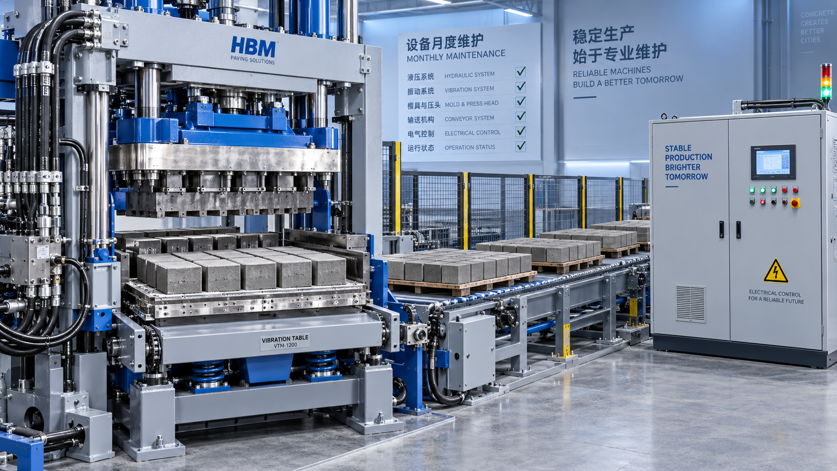
What Monthly Maintenance Does a Paving Block Machine Need?
What maintenance does a paving block machine need monthly? Discover essential checks for hydraulics, molds, vibration, safety, and reliable block quality.