




Custom AAC Plant Design: Which Layout Decisions Impact Output and Energy Use?
When evaluating a custom AAC plant design, the core issue is not simply whether the line can produce autoclaved aerated concrete, but whether its layout can sustain target output with stable energy consumption over years of operation. For technical assessment teams, the best layouts usually reduce repeated handling, shorten transfer distances, balance autoclave loading rhythm, and keep utilities aligned with real production demand rather than theoretical peak values.
That is why layout decisions deserve early scrutiny. In many projects, production bottlenecks and excessive steam or power use are not caused by one machine alone. They often come from how raw material preparation, batching, casting, cutting, pre-curing, autoclaving, and finished product logistics are arranged as one system. A well-planned layout improves throughput, lowers waste, and makes maintenance far easier.
What Is the Real Search Intent Behind Custom AAC Plant Design?
For this topic, the underlying search intent is highly practical. Technical evaluators are usually comparing suppliers, reviewing proposals, or validating whether a proposed plant configuration can meet performance targets. They want to know which design choices actually affect production capacity, steam efficiency, operating stability, and long-term operating cost.
They are not mainly looking for a basic introduction to AAC technology. Instead, they need a framework for judging whether one plant design is stronger than another. That means identifying the layout points that influence output consistency, energy losses, downtime risk, labor intensity, and future expansion. The article is most valuable when it helps readers distinguish between a merely complete line and a genuinely efficient one.
Why Material Flow Is the First Layout Decision to Check
In a custom AAC plant design, material flow is the foundation of overall performance. If lime, cement, gypsum, fly ash or sand slurry, aluminum powder, molds, green cakes, and finished blocks all move through the plant with minimal crossing and backtracking, production becomes easier to stabilize. If paths overlap or require repeated transfers, both output and energy efficiency deteriorate.
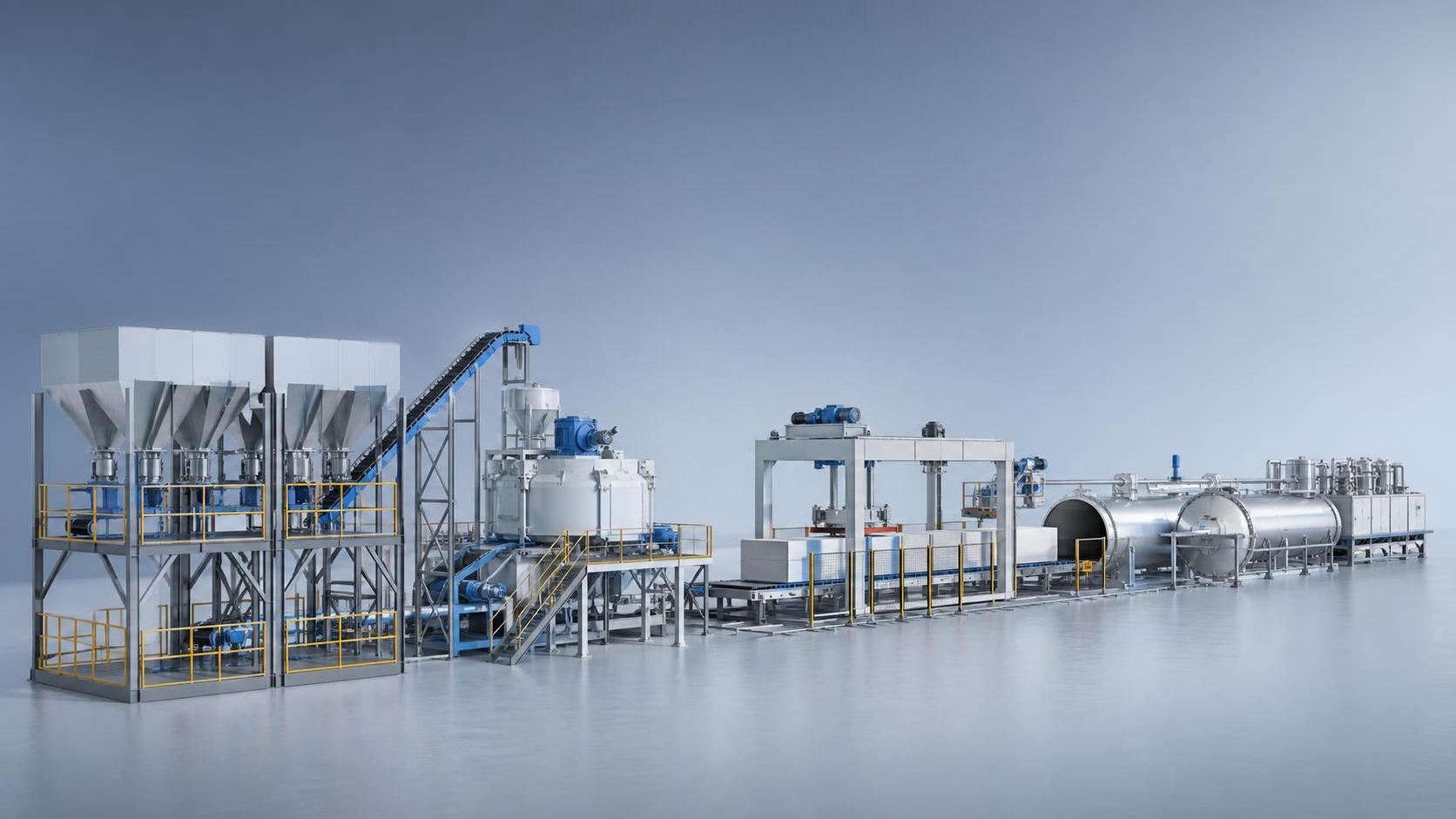
Technical teams should examine whether the layout follows a logical sequence from raw material receiving to storage, dosing, mixing, casting, pre-curing, cutting, autoclaving, separation, packing, and dispatch. Each unnecessary turn, lift, or transfer point adds delay, equipment wear, and operator dependency. Over time, those inefficiencies become structural operating costs.
Good material flow also supports safety and housekeeping. Dust-prone materials should be handled with short enclosed routes. Slurry systems should avoid long piping runs that increase sedimentation risk. Mold and side-plate circulation should be direct and synchronized with casting and demolding cycles. These details strongly affect line rhythm, even when nameplate capacities look similar on paper.
How Raw Material Preparation Influences Throughput and Utility Use
Raw material preparation is often underestimated during layout review. Yet grinding, slurry storage, powder conveying, and dosing precision directly affect both product quality and the smoothness of downstream operations. A plant may have sufficient autoclave capacity, but unstable slurry quality or delayed batching will still reduce real output.
If sand or fly ash grinding is placed too far from slurry storage and casting, pipe lengths increase and pumps work harder. This raises electricity use and introduces more opportunity for pressure drop, clogging, or inconsistent delivery. When storage tanks are undersized, frequent interruptions occur. When oversized without good circulation design, material settlement and quality drift become concerns.
Evaluators should also review whether the batching zone is positioned for direct communication with the control room and casting section. Shorter response time matters. In AAC production, even small deviations in slurry density, temperature, or additive dosing can affect rise behavior, cutting quality, and autoclave performance. Layout should support process control, not separate it from production reality.
Why Casting, Pre-Curing, and Cutting Need Tight Spatial Coordination
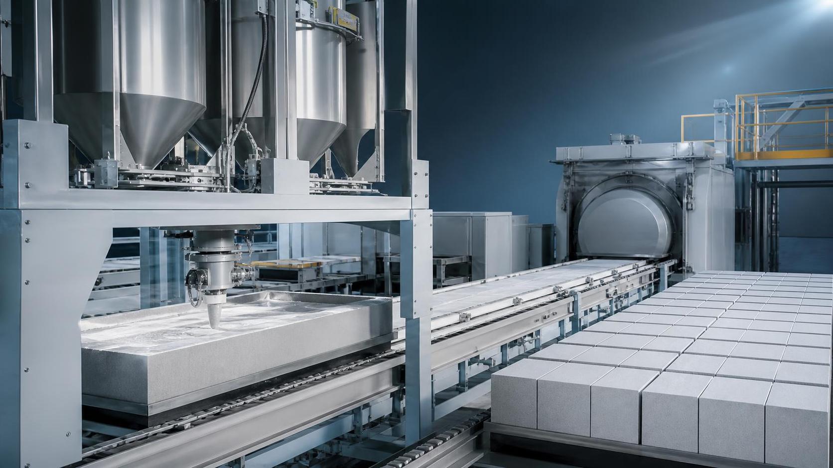
The casting and pre-curing section is where a custom AAC plant design begins to reveal whether it was engineered for flow or simply assembled from equipment lists. The distance between mixer, casting area, pre-curing chamber, and cutting line should be as short and linear as possible. Green cake handling is time-sensitive and vulnerable to variation.
If molds wait too long before entering pre-curing, temperature conditions become less predictable. If transfer routes are long or congested, mold turnover slows and casting cycles lose consistency. When cutting is too far from pre-curing or requires extra crane movement, cake damage risk rises. That reduces yield and creates hidden waste through rejected or downgraded products.
For technical assessment, one useful question is whether the layout protects process timing at every step. AAC output depends not only on machine speed, but also on the reliability of green cake readiness. A compact and synchronized arrangement of casting, pre-curing, tilting, and cutting often delivers more practical capacity than a larger but fragmented workshop plan.
Autoclave Positioning Has a Direct Effect on Steam Efficiency
Among all layout decisions, autoclave positioning has one of the clearest impacts on both output and energy use. Autoclaves should be placed to minimize trolley transfer distance from cutting and to simplify loading and unloading cycles. Long travel paths increase handling time, expose green products to more disturbance, and slow the batch rhythm of the entire line.
Steam distribution is equally important. If autoclaves are positioned far from the boiler house or steam headers are poorly routed, heat loss rises and pressure stability becomes harder to maintain. A technically sound custom AAC plant design keeps steam pipelines short, insulated, and balanced, with attention to condensate recovery and pressure control. These are not secondary details; they affect energy cost every day.
Layout should also avoid traffic conflicts between loaded and empty trolleys. When rail systems cross forklift lanes or require frequent switching, loading delays become normal. In contrast, a clean one-way or loop-based movement pattern allows faster turnover. Higher autoclave utilization often comes less from adding vessels than from improving the movement logic around them.
How Utility Integration Shapes Long-Term Operating Cost
Technical evaluators should pay close attention to utility layout, because energy performance is largely determined before production starts. Steam, compressed air, process water, wastewater return, dust collection, and electrical distribution all perform better when planned as integrated systems rather than afterthoughts around equipment footprints.
For example, poor placement of the boiler house can increase steam line losses. Weak condensate recovery design wastes heat and water. Long compressed air networks cause pressure loss and force compressors to work harder. Inadequate drainage around slurry and cutting zones creates maintenance problems that gradually reduce uptime. These issues are expensive precisely because they are built into the layout.
A robust design also considers service access. Maintenance corridors, valve stations, cable routing, and spare lifting space should be reviewed during technical evaluation. Plants that look compact on drawings can become inefficient in operation if utilities are difficult to inspect or isolate. Good layout reduces not only consumption, but also the duration and frequency of stoppages.
What Layout Choices Usually Limit Real Output
In proposal reviews, nameplate capacity is often presented confidently, but actual daily output depends on the slowest repeating step in the line. The most common layout-related constraints are insufficient mold circulation, cutting queue congestion, autoclave loading imbalance, narrow transfer corridors, and poor synchronization between batching and casting.
Another frequent issue is designing around peak machine capability instead of practical cycle matching. If one section can process more than the next section can absorb, work-in-progress accumulates. That increases waiting time, handling frequency, and quality variation. A technically strong custom AAC plant design balances sections so that throughput is continuous rather than burst-driven.
Readers evaluating supplier proposals should therefore ask for cycle-time logic, not only equipment lists. How many molds circulate per shift? How long is each pre-curing window? How many cakes can be cut and loaded within one autoclave cycle? Where do buffers exist, and are they sufficient? These questions reveal whether claimed capacity is realistic.
How to Assess Expansion Flexibility Without Overbuilding
Many buyers want room for future growth, but expansion planning should be selective. Overbuilding every section from the start can increase capital cost, building volume, and idle energy load without creating immediate value. The better approach is to identify which parts of the layout should be expandable and which should be sized to current demand.
Autoclave foundations, rail corridors, utility headers, and finished goods logistics often deserve forward planning. Some storage and control systems can also be designed with future lines in mind. At the same time, not every auxiliary area needs to be oversized. Technical assessment should focus on whether the layout preserves practical expansion paths without compromising present efficiency.
This is where supplier engineering depth matters. An experienced manufacturer understands how to stage plant growth while maintaining process coherence. Companies with a broad equipment background across masonry and building material machinery, including products such as the QMJ-6A block machine, often bring a wider perspective on production logic, workshop planning, and utility coordination across different plant types.
Which Questions Technical Assessment Teams Should Ask Suppliers
To judge a proposed custom AAC plant design properly, evaluators should move beyond brochure descriptions. Ask suppliers to explain the intended material flow, cycle balance, steam routing, condensate recovery, and maintenance access. Request a layout narrative that shows why each area is positioned where it is, and what bottleneck assumptions were used.
It is also useful to ask how the supplier estimates actual versus theoretical output. What operating hours, product mix, moisture conditions, and curing cycles are assumed? How are downtime allowances handled? Are utility consumption figures based on similar running plants or only design calculations? Clear answers usually indicate stronger engineering discipline.
Another practical checkpoint is whether the design supports operational visibility. Can operators and supervisors quickly identify delays between batching, casting, cutting, and autoclaving? Can maintenance teams reach critical components safely? Can traffic routes support both routine production and abnormal recovery situations? These points often determine whether a plant performs well after commissioning.
Why the Best Layout Is the One That Keeps the Whole Plant Balanced
The strongest custom AAC plant design is rarely the one with the most aggressive single-machine specification. It is the one that keeps every section working in rhythm with the others. Balanced flow reduces waiting, repeated handling, steam waste, and unplanned stoppages. It also improves quality consistency because process timing becomes more stable.
For technical assessment teams, this means layout should be judged as a production system rather than a drawing exercise. Material preparation, batching, casting, cutting, autoclaving, utilities, and logistics must all support one another. A plant can only reach efficient output when the physical arrangement reinforces process discipline every hour of operation.
That is also why experienced manufacturers put significant effort into customization. Site conditions, target capacity, raw material characteristics, product mix, labor model, and energy strategy all shape the right answer. Even where supporting equipment from the same manufacturer portfolio, such as another application of the QMJ-6A block machine, reflects broader production expertise, AAC layout decisions still need to be engineered around the specific operating objective.
Conclusion
For anyone reviewing a custom AAC plant design, the main conclusion is straightforward: layout decisions have a direct and lasting effect on output, steam efficiency, power consumption, labor intensity, and maintainability. The most important areas to evaluate are material flow logic, raw material preparation placement, casting and cutting coordination, autoclave positioning, and integrated utility routing.
Technical assessment teams should therefore prioritize real operating logic over surface-level capacity claims. A good design minimizes transport, balances cycle times, protects process timing, and reduces embedded energy loss. When those fundamentals are right, the plant is far more likely to deliver stable production, lower operating cost, and better long-term return on investment.
Recommend
 Sep 23, 2026
How automatic AAC production line stability affects block quality
Automatic AAC production line stability directly shapes block strength, density, and dimensions. Learn how tighter process control reduces defects, waste, and safety risks.
- Sep 23, 2026
What to check before buying autoclaved aerated concrete equipment
Autoclaved aerated concrete equipment buying guide: learn what to check on line balance, raw materials, energy use, maintenance, and support before choosing a reliable AAC solution.
- Sep 24, 2026
How to reduce downtime caused by worn AAC plant machinery
AAC plant machinery downtime can be cut by spotting wear early, prioritizing critical parts, and using smarter maintenance strategies to keep production stable and costs under control.