


Can One Cutting Machine Handle Different AAC Panel Sizes?
Yes, one cutting machine can handle different autoclaved aerated concrete (AAC) panel sizes, provided that its cutting envelope, wire arrangements and handling equipment cover the required dimensions. The important distinction is between changing the dimensions a machine can physically cut and changing them efficiently, repeatedly and without damaging reinforcement or uncured material.
Panel flexibility is therefore a property of the production line, not just the cutter. A machine may accept several cutting patterns, yet a change in panel length or thickness can also require a different reinforcement cage, repositioned wires, new cutting recipes, and adjustments to separation, curing or packing equipment.
What “different panel sizes” means for the cutting machine
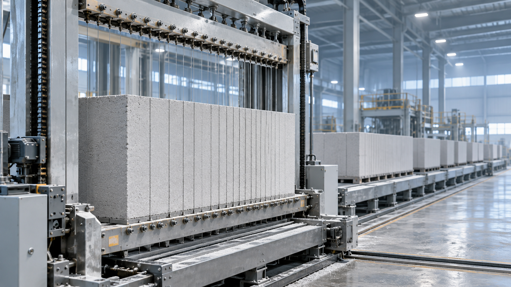
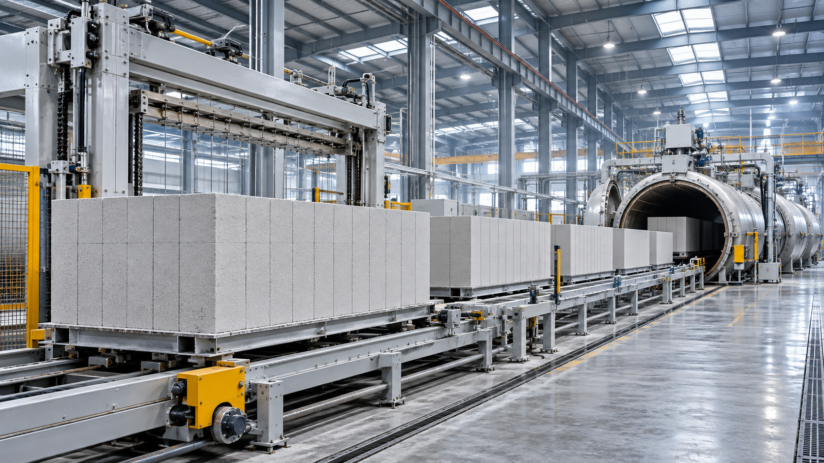
An AAC cake is typically cut after it has gained enough green strength to retain its shape but before autoclave curing. Wires make cuts through the cake in coordinated directions, producing individual units that are subsequently cured. The exact movement of the cake, cutting frame and wires depends on the line design.
Panel dimensions are not all changed in the same way. One dimension may be controlled by the spacing between parallel wires, while another depends on the position of a cross-cut or on how the cake is presented to the cutting system. Before comparing machines, it is useful to map the finished panel’s length, width and thickness to the actual cutting directions of each proposed line. Terms such as “horizontal cut” and “vertical cut” can refer to different physical arrangements when a cake is tilted during handling.
A machine may accommodate a range of panel thicknesses by changing wire positions, for example, while its practical panel length remains constrained by the cake dimensions and cross-cutting arrangement. Similarly, a long panel might fit within the cutter’s advertised maximum length but exceed the capacity of a downstream transfer system. A single maximum dimension does not establish that every combination of length, width and thickness is feasible.
The cutting envelope sets the outer limit
The starting point is the usable cake size and the machine’s permitted cutting area. These determine how the required panels can be arranged within a cake, including any material removed from the top, sides or ends. The nominal mould size alone is not necessarily the same as the usable finished-product envelope: trimming allowances and the condition of the cake edges affect what remains available.
For each intended panel size, a cutting layout should show the number of panels produced from one cake and identify all residual sections. A layout that fits geometrically can still be unattractive if it leaves a large remainder, requires an extra cut or makes the panels difficult to separate. Conversely, two panel sizes that fit the same cake may have very different yields.
Minimum dimensions matter as much as maximum ones. Thin or narrow panels can be more sensitive to wire deflection, vibration and handling damage. The machine may have a theoretical wire spacing smaller than the supplier is prepared to guarantee for a reinforced panel of a particular length. The acceptable range should therefore be assessed as a combination of dimensions, material properties and reinforcement design—not as independent minimum and maximum values.
Wire adjustment determines how easily sizes can change
A cutting system can be flexible in several ways. Some machines use adjustable wire holders that are repositioned for a different pattern; others use interchangeable frames or more automated positioning. Each approach can produce multiple sizes, but the time and work involved in changing between them can differ substantially.
A useful distinction is between adjustment range and changeover capability. Adjustment range describes where wires can be set. Changeover capability includes the steps needed to reach that setting, check it and resume stable production. Those steps can include isolating the machine, moving or replacing wires, setting tension, checking alignment, loading a control recipe and inspecting the first cut cakes.
Automatic positioning does not eliminate every changeover task. Wire condition, tension and cutting-frame alignment still affect the result. Nor does a manual adjustment necessarily make a line unsuitable: it may be economical when production runs are long and the size schedule changes infrequently. The relevant comparison is the expected production time lost and the quality risk for the actual product mix.
For example, a plant producing one panel thickness for several days at a time may accept a longer adjustment procedure. A line expected to alternate between thicknesses within a shift needs a closer look at adjustment access, repeatability and the availability of prepared cutting frames. Changeover time should be defined from the last acceptable cake of one size to the first acceptable cake of the next, rather than only the time required to move the wires.
Reinforcement changes the compatibility question
AAC panels commonly contain corrosion-protected steel reinforcement. The reinforcement must be positioned so that the specified concrete cover is maintained after cutting and curing. A machine that can cut an unreinforced block pattern is not automatically suitable for every reinforced panel pattern.
When panel dimensions change, the reinforcement cage or mesh arrangement may also need to change. Its length, width, position in the mould and clearance from planned cutting planes must match the cutting layout. If a wire intersects reinforcement where it should not, the result can be a damaged wire, a disturbed cage or a rejected product. Even without direct contact, displacement of reinforcement can leave insufficient cover or create inconsistent panel quality.
This makes upstream reinforcement preparation part of size flexibility. A line designed around one cage geometry may require different positioning fixtures or mould arrangements for another. The cutter’s supplier and the reinforcement-system supplier should work from the same panel drawings and cutting plan, especially where equipment is sourced separately.
Panel openings, embedded components or special edge profiles add another layer of complexity. They may require separate processing or dedicated tooling rather than a simple change in wire spacing. A standard straight-wire cutting system should not be assumed to produce every finished detail solely because it can cut the panel’s overall dimensions.
Green-cake condition affects every size change
Cutting accuracy depends on the cake arriving at the cutter in a suitable condition. If it is too soft, wires and handling movements can deform the material or disturb reinforcement. If it is too hard, cutting forces can rise and wires may be more prone to deflection or breakage. The workable condition depends on the mix, process settings, cake dimensions and equipment design.
Changing a cutting pattern does not necessarily require a new mix, but a line producing substantially different panel geometries should be checked for its ability to deliver consistent green strength across those products. Thin panels, for instance, leave less margin for deformation during separation and transfer. Consistency matters across the whole cake as well as between batches: one acceptable area does not guarantee that every panel will cut and separate cleanly.
Upstream capacity must also keep the cutting line supplied at the intended rate. A practical question is: “How do I choose the right capacity for an AAC slurry mixer?” The answer starts with the slurry volume required per mould, batching cycle time and planned mould-release interval, while accounting for usable mixer capacity and the rest of the dosing and pouring sequence. A larger mixer alone does not guarantee more output if pouring, rising, cutting or curing is the bottleneck. Equally, frequent changes in cake or mould volume can affect how efficiently the mixer is used.
Cutting speed is not the same as line output
A supplier may quote a cutting cycle time or a nominal production capacity, but neither figure alone shows the output for a mixed panel schedule. Effective output depends on the number of usable panels per cake, the time between cakes, changeovers, rejected material and downstream constraints.
A simple planning calculation can expose the difference. Suppose a cutting layout produces 20 acceptable panels per cake and the line completes 10 cakes during an operating period. The theoretical output for that period is 200 panels before losses. If a different panel size yields 16 panels per cake, the same cake rate produces 160 panels. The machine has not slowed down, but the number of panels produced has changed. These figures are illustrative, not equipment performance claims.
Comparisons are often clearer in finished panel volume as well as panel count, because panel sizes differ. Both measures should be considered alongside the usable area required by customers. Any capacity calculation should state whether it includes trimming losses, planned changeovers, maintenance stops and rejected panels; otherwise, apparently comparable quotations may use different assumptions.
Downstream handling can be decisive. A cutting machine may process a long, thin panel, but lifting and separation equipment must support it without unacceptable bending or breakage. The panel arrangement must also fit curing carriers and the autoclave loading system used by the plant. After curing, unloading, stacking and packaging equipment must accommodate the same range. The line’s usable size range is limited by the least flexible stage.
What to establish before specifying one machine
Instead of asking whether a cutter can produce “multiple sizes,” provide a product matrix with the intended panel lengths, widths and thicknesses, including the combinations expected to run together. Include reinforcement drawings, required dimensional tolerances, planned production volumes and the expected frequency of size changes.
For each representative size, request a proposed cake and cutting layout showing panel count, trimming, wire positions and reinforcement clearance. The largest and smallest panels deserve attention, but so do awkward intermediate sizes that leave poor yield or require an unusual wire arrangement. A supplier’s confirmation should cover the complete dimension combinations rather than only separate maximum and minimum figures.
Changeover details should be equally specific. Identify which settings are automatic, which require manual work, whether additional frames or fixtures are needed, and how the new pattern is checked before full production resumes. Where performance guarantees are offered, their scope should distinguish cutter cycle time from whole-line output and state the product, cake and operating conditions on which the figures are based.
A single cutting machine is a sound choice when the required panel range fits a practical set of cutting layouts and the surrounding equipment can support the same range. The strongest basis for that decision is not the number of sizes listed in a brochure, but a demonstrated production arrangement for the panels that will actually be made.
Recommend
 Nov 11, 2026
How Many Concrete Roof Tiles Can a Machine Produce per Day?
Can one cutting machine handle different AAC panel sizes? Explore the answer and learn how to calculate realistic daily concrete roof tile output.
- Nov 11, 2026
Can One Cutting Machine Handle Different AAC Panel Sizes?
How do I choose the right capacity for an AAC slurry mixer? Explore sizing factors and learn how mixer capacity supports flexible AAC panel production.
- Nov 10, 2026
How Do Semi-Automatic and Fully Automatic AAC Lines Compare?
How does a semi-automatic AAC line compare with a fully automatic one? Explore costs, capacity, labor and maintenance to choose the right solution for your plant.