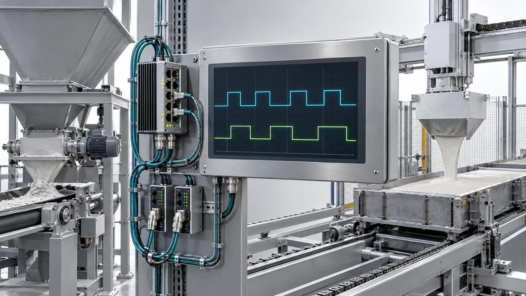

Automatic AAC Production Line Integration Challenges: PLC Communication Gaps Between Feeding, Casting & Cutting Units
Integrating an automatic AAC production line requires precise, real-time coordination among feeding, casting, and cutting units—yet technical evaluators frequently encounter operational halts or quality deviations traced back to PLC communication gaps. These are not isolated hardware failures but systemic integration flaws: mismatched data structures, unsynchronized cycle timing, and protocol-level incompatibilities between subsystems from different vendors or legacy upgrades. At Shandong Hongfa, where aerated concrete block production lines have been engineered and field-validated across 30+ years and four ISO9001-certified manufacturing bases, such gaps are diagnosed not by symptom alone but through layered signal analysis—starting at the I/O mapping layer and extending into task-level execution logic.
Where Communication Breakdowns Actually Occur
PLC communication issues in automatic AAC lines rarely stem from network cabling or physical layer faults. Instead, they manifest at three functional boundaries:
- Feeding-to-casting handoff: The feeding unit’s batch completion signal must trigger casting mold positioning *before* slurry discharge begins. A 120–180 ms timing misalignment—within typical scan cycle tolerances—causes either premature mold movement (slurry spillage) or delayed positioning (inconsistent block dimensions).
- Casting-to-cutting state synchronization: The casting unit reports “cure status” as a Boolean flag, while the cutting unit expects a multi-state enumeration (e.g., “green,” “pre-hardened,” “ready”). Without explicit state translation logic, the cutter defaults to “not ready,” stalling the line despite adequate curing time.
- Shared resource arbitration: Both casting and cutting units access the same conveyor tracking system via Modbus TCP—but without a master arbitration PLC, concurrent read/write requests cause register corruption. This results in lost position data for cut-length calculation, leading to dimensional drift over successive batches.
Protocol Mapping Is Not Just About Compatibility—It’s About Semantics
Many evaluators assume that selecting a common industrial protocol (e.g., EtherNet/IP or Profinet) resolves interoperability. In practice, identical protocols carry divergent semantic interpretations. For example:
- A “feed_complete” tag in the feeding PLC may be mapped to a generic “status_bit_7” in the casting PLC’s configuration—without documented cross-reference, engineers misinterpret its activation threshold.
- The casting unit uses a 16-bit integer for temperature reporting (0–65535 = 0–100°C), while the cutting unit expects a 32-bit floating-point value. Unconverted data appears as overflow errors or nonsensical values in HMI trend logs.
- Alarm codes are vendor-specific: “E421” in the feeding unit means “conveyor jam,” but the same code in the cutting unit signals “laser calibration timeout.” No shared alarm dictionary means operators respond to false positives or miss critical events.
At Hongfa, this is addressed during commissioning—not with generic protocol converters, but with custom function blocks that enforce semantic alignment: type-safe data conversion, state-machine-based handoff validation, and centralized alarm code translation tables embedded directly in the master control logic.
Timing Misalignment: Beyond Scan Cycle Specifications
PLC scan cycles are often cited as the root of timing issues—but actual latency originates from deeper layers. Consider a typical sequence:
- Feeding PLC detects batch completion → triggers output bit.
- Signal travels via hardwired DI input to casting PLC → introduces 5–10 ms electrical delay.
- Casting PLC reads input in next scan cycle → adds up to 30 ms (if scan time is 30 ms).
- Casting PLC executes positioning logic → outputs command to servo drive.
- Servo drive processes command → mechanical response delay (15–40 ms depending on load).
The cumulative effect—up to 85 ms—exceeds the ±25 ms tolerance window required for synchronized mold positioning. Solutions require layered mitigation: hardware-level signal conditioning (e.g., opto-isolated fast-response inputs), deterministic task scheduling within the PLC (separate high-priority tasks for handoff signals), and mechanical design adjustments (e.g., pre-positioning actuators during slurry filling rather than waiting for full batch confirmation).
Data Integrity Checks That Go Beyond Ping Tests
Network uptime does not guarantee data fidelity. Evaluators should verify integrity using these field-tested methods:
- Tag consistency audit: Compare raw register values for key process variables (e.g., mold position, slurry temperature, cutter speed) across all PLCs simultaneously—not just whether values are present, but whether they differ by more than 0.5% across units sharing the same sensor source.
- Handoff sequence logging: Enable timestamped event logging on both sides of each inter-unit interface (e.g., “feed_complete asserted” + “casting_position_start triggered”) and measure delta time across 50 consecutive cycles. Consistent deltas >35 ms indicate systematic timing misalignment; erratic deltas suggest network jitter or CPU overload.
- State transition validation: Monitor whether state changes propagate unidirectionally and atomically. If the casting unit transitions to “mold_filled” while the cutting unit remains in “idle” for >2 cycles—and no handoff signal was logged—the issue lies in missing or misconfigured event triggers, not network bandwidth.
When to Rely on Hardware Integration vs. Software Bridging
Not all communication gaps warrant protocol gateways or OPC UA servers. Evaluate based on signal criticality:
Hongfa’s automatic AAC production line designs embed this tiered approach—using deterministic hardware links for time-bound actions and standardized software interfaces only where flexibility outweighs timing risk.
Diagnostic Prioritization for Technical Evaluators
When troubleshooting live line interruptions:
- First isolate whether the fault occurs at a specific handoff point (e.g., only after feeding completes) or across multiple transitions—this indicates whether the issue is localized or systemic.
- Check raw I/O status on both PLCs *during* the handoff—not just in HMI history—since buffered displays mask transient signal loss.
- Verify clock synchronization accuracy (PTP or NTP) if timestamps are used for correlation; >100 ms skew invalidates cross-PLC event analysis.
- Review firmware revision compatibility notes—not just version numbers, but confirmed interoperability matrices published by each vendor for the exact hardware series deployed.
No single test confirms resolution. Validation requires observing at least three consecutive successful handoffs under full production load, with measured timing deltas within ±15 ms and zero state mismatches in logged sequences.
Next:No more content
Recommend
 Sep 16, 2026
Automatic AAC Production Line Integration Challenges: PLC Communication Gaps Between Feeding, Casting & Cutting Units
Discover how PLC communication gaps disrupt your automatic AAC production line—feeding, casting & cutting unit integration challenges revealed with actionable fixes.
- Sep 15, 2026
What wall panel production machine specifications support prefab construction efficiency?
wall panel production machine for prefab construction: Discover specs that drive real-world efficiency—precision, adaptability, uptime & integrated support.
 May 07, 2026
The various preparatory works for aerated concrete equipment should meet the designated standards.
Autoclaved aerated concrete (AAC) equipment typically features two production processes: fly ash AAC block